
Chapter 4 Building Business Process Diagrams
Processes (BPM)
A process is a manual or automated action, such as "Process order", or "Send a mail".
You can decompose processes in order to analyze their actions more closely, and further decompose your sub-processes until you reach an appropriate level of detail. A process that is not decomposed is called an atomic process (or activity) (see Decomposing processes).
A process can be created in the following diagrams with any target languages:
- Process Hierarchy Diagram – each process forms part of a hierarchy, which begins with a single top-level process, and is decomposed into sub-processes. Each decomposed process can be analyzed in its own business process diagram.
In the following example, the top-level Design process is decomposed into three sub-processes named Analyze needs, Analyze tasks, and Analyze audience:

For more information, see the "Building Process Hierarchy Diagrams" chapter.
- Business Process Diagram – processes can be created in each of the three types of business process diagrams:
- Top-level diagram – the process is a top-level process, or global service, that interacts with partners.
In the following example, the top-level OrderCollaboration process interacts with the Buyer and Seller partners:

For more information, see Top-Level Diagram Basics.
- Choreography diagram – processes are linked together in a control flow, which passes from one or more starts to one or more ends. When the process gains control, it performs its actions and then, depending on the result of the action, the flow is passed to another process.
PowerDesigner allows you a great deal of flexibility in your analysis of your processes. You can simply link processes together to show the high-level control flow, or refine your model by specifying their implementation (see Specifying implementation types).
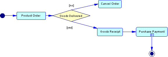
In the following example, the path of an order depends on whether the product can be delivered or not. If yes, the control flow passes through the Goods Receipt process, then through the Purchase Payment process, whose details are displayed in a sub-diagram. Finally the control flow goes to Finish:

For more information, see Choreography Diagram Basics.
- Data Flow Diagram – processes are locations where data are transformed.
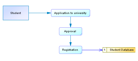
In the following example, data are sent by the external Student entity through three sequencing processes, and finally are stocked into the Student Database data store:

For more information, see the "Working with Data Flow Diagrams" chapter.
|
Copyright (C) 2008. Sybase Inc. All rights reserved.
|

|


