
Chapter 4 Building Conceptual Data Models
In a dependent relationship, one entity is partially identified by another. Each entity must have an identifier. In some cases, however, the attributes of an entity are not sufficient to identify an occurrence of the entity. For these entities, their identifiers incorporate the identifier of another entity with which they have a dependent relationship.
An entity named Task has two entity attributes, TASK NAME and TASK COST. A task may be performed in many different projects and the task cost will vary with each project. To identify each occurrence of TASK COST the unique Task entity identifier is the compound of its Task name entity attribute and the Project number identifier from the Project entity.
In the resulting model, a triangle just before the termination point of the relationship indicates a dependent relationship. The triangle points away from the dependent entity.
For example, here Entity B depends on Entity A.
The bar indicates that the relationship in not only dependent, but also mandatory. The single contact point indicates the one-to-one cardinality of the relationship. In this case, for each occurrence of Entity B there must be only one occurrence of Entity A.
The tip of the triangle shown above has a bar to note a mandatory relationship: every occurrence of Entity A requires an occurrence of Entity B.
For more information on IDEF1X notation, see section CDM options in chapter Conceptual Data Model Basics.
![]() To define a dependent relationship:
To define a dependent relationship:
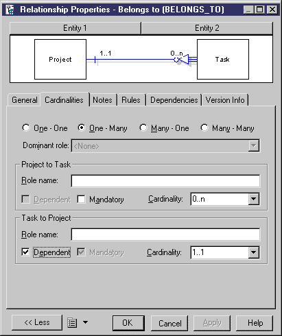
The property sheet below shows that the Task entity is dependent on the Project entity.

The relationship pictured here expresses this dependency.

The circle at the tip of the triangle indicates that occurrences of the Project entity do not require an occurrence of the Task entity. But an occurrence of the Task entity requires an occurrence of the Project entity on which it depends.
| Copyright (C) 2005. Sybase Inc. All rights reserved. |

| |