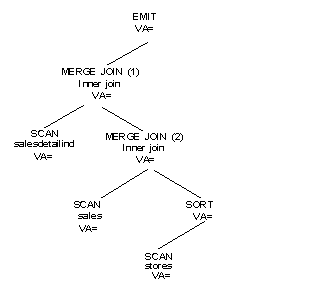
The position of each operator in the tree determines its order of execution. Execution starts down the left-most branch of the tree and proceeds to the right. To illustrate execution, this section steps through the execution of the query plan for the example in the previous section. Figure 2-1 shows a graphical representation of the query plan.

To generate a result row, the EMIT operator
calls for a row from its child, the MERGE JOIN operator
(1), which calls for a row from its left child, the SCAN operator
for salesdetailind. When EMIT receives
a row from its left child, MERGE JOIN operator
(1) calls for a row from its right child, MERGE
JOIN operator (2). MERGE
JOIN operator (2) calls for a row from its
left child, the SCAN operator
for sales.
When it receives a row from its left child, MERGE
JOIN operator (2) calls for a row from its
right child, the SCAN operator.
The SCAN operator is a
data-blocking operator. That is, it needs all of its input rows
before it can sort them, so the SORT operator
keeps calling for rows from its child, the SCAN operator for stores,
until all rows have been returned. Then the SORT operator
sorts the rows and passes the first row to the MERGE
JOIN operator (2).
The MERGE JOIN operator
(2) keeps calling for rows from either the left or right child operators
until it gets two rows that match on the joining keys. The matching
row is then passed up to MERGE JOIN operator
(1). MERGE JOIN operator
(1) also calls for rows from its child operators until a match is
found, which is then passed up to the EMIT operator
to be returned to the client. In effect, the operators are processed
using a left-deep postfix recursive strategy.
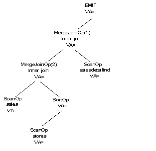
Figure 2-2 shows a graphical representation of an alternate query plan for the same example query. This query plan contains all of the same operators, but the shape of the tree is different.
Figure 2-2: Alternate query plan

The showplan output corresponding to the query plan in Figure 2-2 is:
QUERY PLAN FOR STATEMENT 1 (at line 1). 6 operator(s) under root The type of query is SELECT. ROOT:EMIT Operator |MERGE JOIN Operator (Join Type: Inner Join) | Using Worktable3 for internal storage. | Key Count: 1 | Key Ordering: ASC | | |MERGE JOIN Operator (Join Type: Inner Join) | | Using Worktable2 for internal storage. | | Key Count: 1 | | Key Ordering: ASC | | | | |SCAN Operator | | | FROM TABLE | | | sales | | | Table Scan. | | | Forward Scan. | | | Positioning at start of table. | | | Using I/O Size 2 Kbytes for data pages. | | | With LRU Buffer Replacement Strategy for data pages. | | | | |SORT Operator | | | Using Worktable1 for internal storage. | | | | | | |SCAN Operator | | | | FROM TABLE | | | | stores | | | | Table Scan. | | | | Forward Scan. | | | | Positioning at start of table. | | | | Using I/O Size 2 Kbytes for data pages. | | | | With LRU Buffer Replacement Strategy for data pages. | | |SCAN Operator | | FROM TABLE | | salesdetail | | Index : salesdetailind | | Forward Scan. | | Positioning at index start. | | Index contains all needed columns. Base table will not be read. | | Using I/O Size 2 Kbytes for index leaf pages. | | With LRU Buffer Replacement Strategy for index leaf pages.
The showplan output conveys the shape of the query plan by using indentation and the pipe (“|”) symbol to indicate which operators are under which and which ones are on the same or different branches of the tree. There are two rules to interpreting the tree shape:
The pipe “|” symbols form a vertical line that starts at the operator’s name and continue down past all of the operators that are under it on the same branch.
Child operators are indented to the left for each level of nesting.
Using these rules, the shape of the query plan in Figure 2-2 can be derived from the previous showplan output with the following steps:
The ROOT or EMIT operator
is at the top of the query plan tree.
MERGE
JOIN
operator
(1) is the left child of the ROOT. The
vertical line that starts at MERGE JOIN operator
(1) travels down the length of the entire output, so all of the
other operators are below MERGE JOIN operator
(1) and on the same branch.
The left child operator of the MERGE
JOIN operator (1) is MERGE
JOIN operator (2).
The vertical line that starts at MERGE
JOIN operator (2) travels down past a SCAN,
a SORT, and another SCAN operator
before it ends. These operators are all nested as a subbranch under MERGE
JOIN operator (2).
The first SCAN under MERGE
JOIN operator (2) is its left child, the SCAN of
the sales table.
The SORT operator
is the right child of MERGE JOIN operator
(2) and the SCAN of the stores table
is the only child of the SORT operator.
Below the output for the SCAN of
the stores table, several vertical lines end.
This indicates that a branch of the tree has ended.
The next output is for the SCAN of
the salesdetail table. It has the same indentation
as MERGE JOIN operator
(2), indicating that it is on the same level. In fact, this SCAN is
the right child of MERGE JOIN operator
(1).
![]() Most operators are either unary or binary. That is,
they have either a single child operator or two child operators
directly beneath. Operators that have more than two child operators
are called “nary”. Operators that have no children
are leaf operators in the tree and are termed “nullary.”
Most operators are either unary or binary. That is,
they have either a single child operator or two child operators
directly beneath. Operators that have more than two child operators
are called “nary”. Operators that have no children
are leaf operators in the tree and are termed “nullary.”
Another way to get a graphical representation of the query plan is to use the command set statistics plancost on. See Adaptive Server Reference Manual: Commands for more information. This command is used to compare the estimated and actual costs in a query plan. It prints its output as a semigraphical tree representing the query plan tree. It is a very useful tool for diagnosing query performance problems.