

Chapter 7 Data Transformations Basics
Data Transformations Overview
In most enterprises, information is stored in multiple databases, data warehouses and applications. A situation that requires the recombination and transformation of data coming from diverse sources into new formats for replication reporting or other consumption.
ETL (Extract Transform and Load) and EII (Enterprise Information Integration) are two technologies that address this need:
- ETL is a process in data warehousing that refers to three separate functions combined into a single programming tool:
- Extract – reads data from a specified source system.
- Transform – manipulates the extracted data to convert it for particular specialized consumption.
- Load – writes the resulting data to a target.
- EII combines raw data by orchestrating and organizing queries to diverse source systems without any previous aggregation of the content. The data is not permanently moved into a new location.
The PowerDesigner Information Liquidity Model (ILM) lets you model and document ETL and EII processes in a rich graphical environment, supported by sophisticated metadata. By modeling your transformations in PowerDesigner, you can benefit from its powerful traceability and impact analysis features.
The ILM lets you model and analyze data transformations in high-level and detailed views as follows:
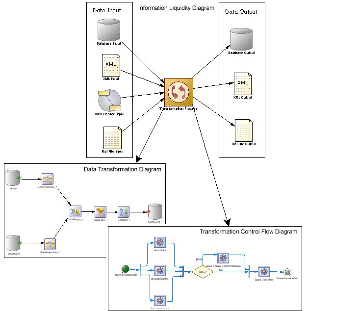
- Information liquidity diagram – high-level diagram, which enables you to model a high-level view of your data transformations by specifying:
- Input sources – can be:
- Databases (via PDMs)
- XML documents (via XSMs)
- Business Processes (via BPMs)
- Flat files such as .CSV and .XLS
- Transformation process – where the transformations occur. It contains lower level detailed transformation diagrams (see Transformation Processes).
- Output sources – can be:
- Databases (via PDMs)
- XML documents (via XSMs)
- Flat files such as .CSV and .XLS
- Data transformation diagram – low level diagram, which enables you to model a transformation task by specifying how data is extracted from data inputs, transformed by actions and loaded into data outputs. Data inputs and outputs are linked to the input and output sources specified in the high-level diagram.
- Transformation control flow diagram – low level diagram, which enables you to specify the sequence of execution of a series of tasks.
The following example shows how input and output sources can be linked to a transformation process at a high level, and how the transformation is modeled in the lower level diagrams:
|
Copyright (C) 2008. Sybase Inc. All rights reserved.
|
|