![]()
![]()
Chapter 3 Building Physical Diagrams
To set Model Settings, select Tools→Model Options or right-click the diagram background and select Model Options from the contextual menu.
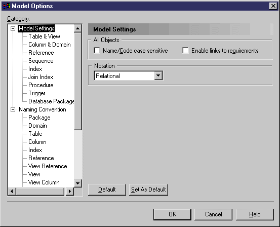
The options on this page affect all the objects in the model, including those already created, while changes to the object-specific options on the sub-category pages only affect objects created subsequently.
You can set the following options on this page:
| Option | Function |
|---|---|
| Name/Code case sensitive | Specifies that the names and codes for all objects are case sensitive, allowing you to have two objects with identical names or codes but different cases in the same model.
If you change case sensitivity during the design process, we recommend that you check your model (Tools→Check Model) to verify that your model does not contain any duplicate objects. |
| Enable links to requirements | Displays a Requirements tab in the property sheet of every object in the model.
Requirements are descriptions of customer needs that must be satisfied during the development process, and are defined in requirements models. The Requirements tab allows you to attach requirements to objects in your model. These attached requirements are kept synchronized with your requirements model. For more information on requirements, see the Requirements Model User's Guide . |
| Notation | Specifies the use of one of the following notation types for the model:
When you change notation, all symbols in all diagrams are updated accordingly. If you switch from Merise to IDEF1X, all associations are converted to relationships. |
| Copyright (C) 2005. Sybase Inc. All rights reserved. |
| |