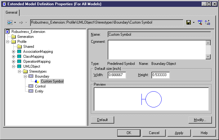
You are going to define a custom symbol for UMLObjects related to the Boundary, Control, or Entity stereotypes. The Custom Symbol feature lets you apply the standard robustness graphics into your communication diagram.
- Double-click the arrow beside Robustness Extension in the list of extended model definitions to display the resource editor.
-
Right-click stereotype Boundary in the UMLObject category and select New > Custom Symbol.
A custom symbol is created.
-
Click the Modify button.
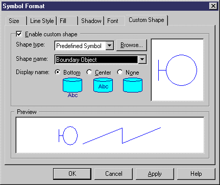
The Symbol Format dialog box is displayed.
- Click the Custom Shape tab.
- Select the Enable Custom Shape check box.
- Select Predefined Symbol in the Shape Type list.
-
Select Boundary Object in the Shape Name list.
-
Click OK.
The custom symbol is displayed in the Preview box.
-
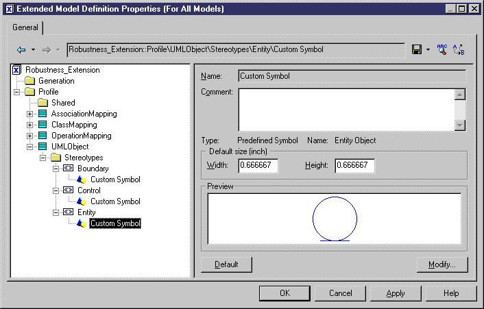
Repeat steps 2 to 8 for the following stereotypes:
-
Click OK in each of the dialog boxes.
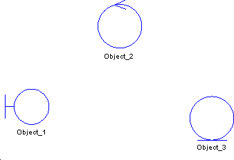
The symbol of the object you had previously created changes according to its stereotype:
-
In the communication diagram, create an object corresponding to each stereotype.
Your diagram now contains 3 objects with different symbols corresponding to different stereotypes.
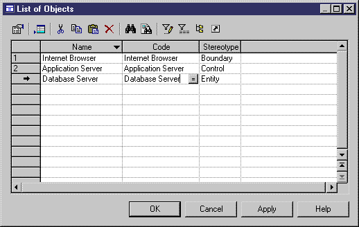
- Select Model > Objects to display the list of objects.
-
Click the Customize Columns and Filter tool in the list toolbar and select Stereotype in the list of columns.
The object stereotypes appear in the list. You are going to define the name and code of each object based on their stereotype.
Object
Stereotype
Name & Code
Object_1
<<Boundary>>
Internet Browser
Object_2
<<Control>>
Application Server
Object_3
<<Entity>>
Database Server
- Click OK in the List of Objects.
- Drag the actor Customer from the Browser to the communication diagram in order to create a symbol for Customer.
