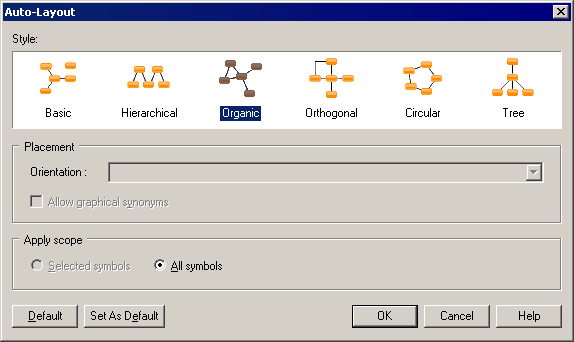
The auto-layout command automatically rearranges symbols in diagrams in order to avoid node overlaps, link intersections with nodes and others links, or long distances between related nodes.
Note that auto-layout is not available for the OOM sequence diagram or any diagrams containing swimlanes.
- Select to open the Auto-Layout window.
-
Choose one of the available styles. Note that depending on the diagram from which you launch auto-layout, some styles may not be available.
-
Basic – Suitable for simple diagrams.
-
Hierarchical – Highlights the main direction or flow within a directed graph. You can additionally specify an orientation for the flow within the graph.
-
Organic – For undirected graphs.
-
Orthogonal - For undirected graphs. You can additionally specify an orientation for the flow within the graph.
-
Circular – Produces interconnected ring and star topologies to emphasize group and tree structures within a network. You can additionally specify a cycle or radiation shape.
-
Tree – For directed or undirected trees. You can additionally specify an orientation for the flow within the graph.
-
- Specify if you want to apply the auto-layout to only selected or all symbols.
-
Click OK to apply the auto-layout and return to the diagram.
Note:
You can, at any time, click the default button to revert to the default auto-layout settings. Click the Set As Default button to set the currently selected style as the default.
