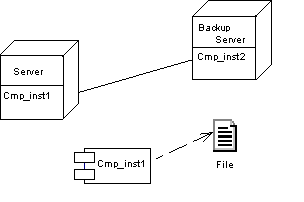
A deployment diagram is a UML diagram that provides a graphical view of the physical configuration of run-time elements of your system.
The deployment diagram provides a view of nodes connected by communication links. It allows you to design nodes, file objects associated with nodes that are used for deployment, and relationships between nodes. The nodes contain instances of component that will be deployed into and execute upon database, application or web servers.

Deployment diagrams are used for actual deployment of components into servers. A deployment can represent the ability to use instances.
You use the deployment diagram to establish the link to the physical architecture. It is suitable for modeling network topologies, for instance.
You can build a deployment diagram to show the following views, from a high level architecture that describes the material resources and the distribution of the software in these resources, to final complete deployment into a server: